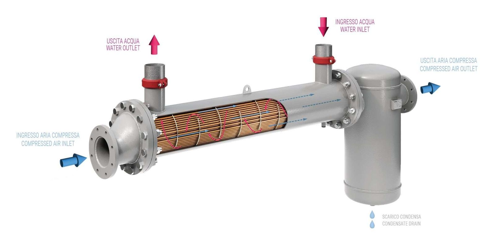

The counter-current heat exchanger allows the compressed air temperature to be reduced to the required conditions, optimising the downstream process. This is the case for adsorption dryers which prefer moderate inlet temperatures achievable with the WFR. The air temperature obtained is slightly higher than the water temperature.
Cooling compressed air, which is in most cases humid, leads to the formation of condensate, which can be separated by a cyclone FTC or WCS condensate separator installed at the heat exchanger outlet.
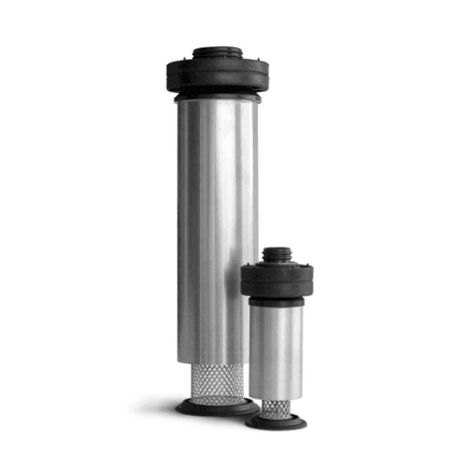
FTC separators in our FT series, have an aluminium body and cyclone cartridge and are equipped with an automatic float-controlled condensate drain.
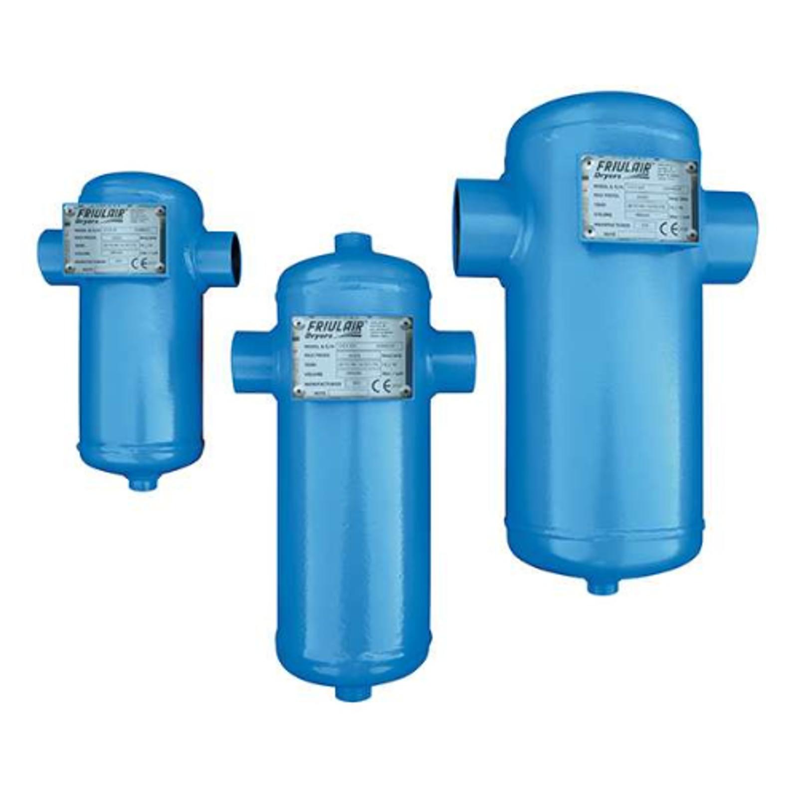
WCS separators have a carbon steel body and a cyclone separator with manual drain.
DESIGN CONDITIONS
- Maximum compressed air inlet temperature: 150°C (FTC 120°C)
- Maximum compressed air pressure: 16 barg
- Maximum water inlet temperature: 90°C
- Maximum water pressure: 10 bar
- Minimum ambient temperature: 1°C
Model | Flow rate | ||
[m3/h] | [lt/min] | [m3/min] | |
WFR27 | 160 | 2667 | 2.7 |
WFR42 | 250 | 4167 | 4.2 |
WFR75 | 450 | 7500 | 7.5 |
WFR125 | 750 | 12500 | 12.5 |
WFR160 | 1000 | 16667 | 16.7 |
WFR270 | 1600 | 26667 | 26.7 |
WFR350 | 2100 | 35000 | 35 |
WFR450 | 2700 | 45000 | 45 |
WFR560 | 3400 | 56667 | 56.7 |
WFR800 | 4800 | 80000 | 80 |
WFR1000 | 6200 | 103333 | 103.3 |
WFR1250 | 7500 | 125000 | 125 |
WFR1800 | 11000 | 183333 | 183.3 |
Performance referred to: compressor air intake conditions 25°C/ rh 50%; compressed air inlet temperature 120°C; compressed air inlet pressure 7 barg; water inlet temperature 20°C; compressed air outlet temperature +10°C compared to water inlet temperature; outlet relative humidity 100%.
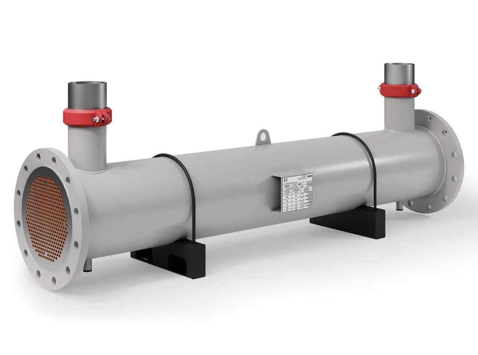
- WFR – Configuration StandardShell and tube exchanger, built with copper tubes, and shell and tube carbon steel plates. Including supporting brackets.
- WFR + FTC Configuration n°1Shell and tube exchanger, built with copper tubes, and shell and tube carbon steel plates. FTC cyclone separator with aluminium body and interchangeable cyclone cartridge. Float-controlled condensate drain.
- WFR + FTC + REDUCER Configuration n°2Shell and tube exchanger, built with copper tubes, and shell and tube carbon steel plates. FTC cyclone separator with aluminium body and interchangeable cyclone cartridge. Float-controlled condensate drain. Tube input reducerWFR + WCS Configuration n°3Shell and tube exchanger, built with copper tubes, and shell and tube carbon steel plates. WCS cyclone separator with carbon steel body. Manual condensate drain.
- WFR + WCS + REDUCER Configuration n°4Shell and tube exchanger, built with copper tubes, and shell and tube carbon steel plates. WCS cyclone separator with carbon steel body. Manual condensate drain.
- Configurations 1/2/3/4 are for assembly. They are supplied with the screws, nuts and gaskets required to assemble the components. Including supporting brackets. The exchanger can be horizontally or vertically installed on request.